ModelMRG – Adjustable Thermostats

This thermostat has a brass body machined from solid drawn rod, Front Copper Tip. All the internal components and spot welded and the contacts are made of solid silver. This provide the thermostat with a long life. The body of the thermostat is double sealed and it is not affected by varnish, dust, fumes, gases, etc. The lead wires are Teflon insulated and can with stand high temperature.

SPECIAL FEATURES :-

  • Solid brass body for strength
  • Available with Normally Open (N.O.) or Normally Closed (N.C.) contacts
  • Better heat sensing capability
  • 1/2″ BSP threading for easy mounting
  • Solid silver contacts for long life of 1,00,000 operations
  • Snap action bimetal thermostat
  • Teflon insulated lead wires
  • Available in any temperature from 60C to 160C

Technical Specifications :-

Voltage Upto 250 VAC or 24 VDC
 Continuous Load Upto 8 AMPS
 Maximum Load  Switching  Capacity 30 AMPS
 Switching Action SPST Normally Closed (N.C.) contacts which open with a snap action at preset temperature. Also available Normally Open (N.O.) contacts which close with a snap action at preset temperature.
 Flash-over Voltage Exceeds 2 KV between body & leads.
 Endurance (Life) Exceeds 100,000 operations (tripping).
 Trip Temperature Available preset for any trip temperature between 60 ± 5 C to 160 ± 5 C specified by customer. Trip temperature not adjustable.
 Reset Temperature Reset temperature (restart temp) approx. 15 ± 5 C below trip temperature.

APPLICATIONS:-

  • Monitoring Temperature of liquids
  • Over Temperature protection of Oil filled transformers
  • Car Radiators and engines
  • Hydraulic lines and tanks
  • Pipelines for fluids and hot gases

Motors & Pumps

Motor Thermal Protector model BPM is the best suited thermostat for over-temperature and burnout protection of all types of AC and DC motors, electric motors, single and three phase motors, induction motors, and all pumps.

Motor Protector Thermostat

Description of Motor Thermal Overload Protector

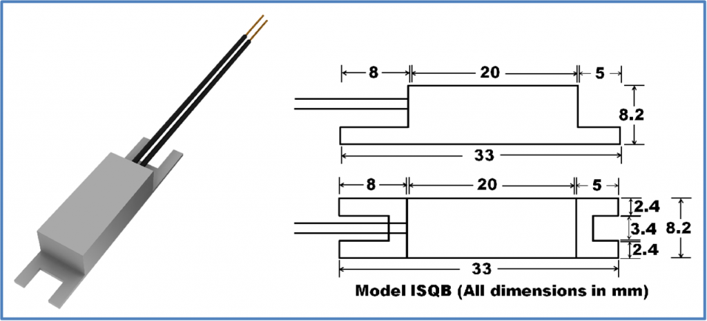
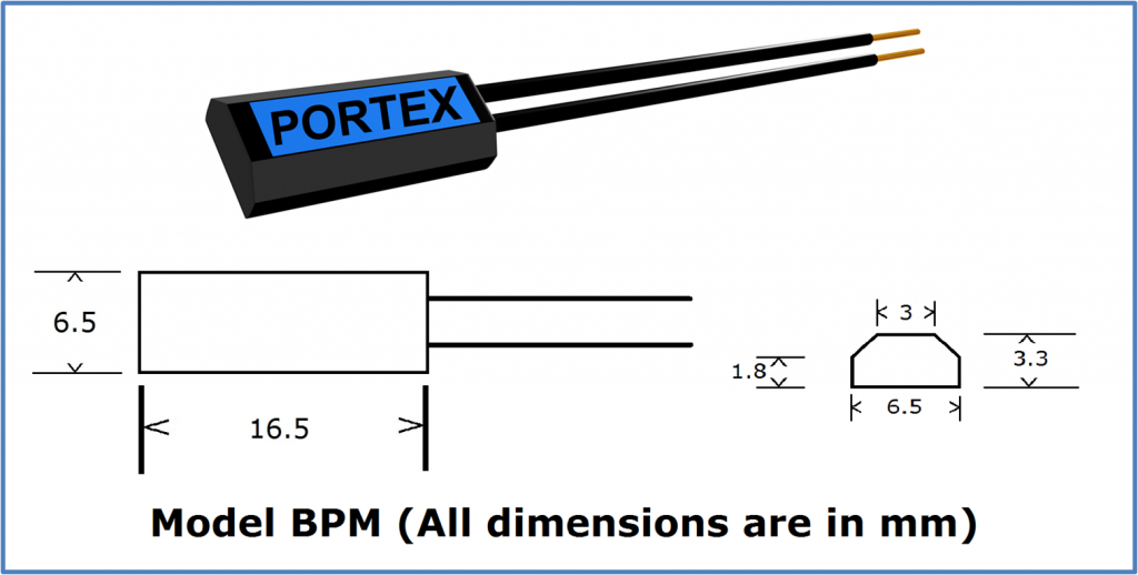
Motor thermal protector model BPM has been developed by our engineering department after extensive R&D for over temperature and burn out protection of all electric motors and pumps. It is the smallest thermal overload protector in our entire range of thermostats. Due to its small size, this thermostat is very sensitive to temperature rise and current overload. This thermal overload protector has a snap acting bimetal strip and a beryllium copper blade. Due to this there is quick make and break switching and there is no sparking when the thermal cutout switches off the motor. The internal contacts are made of solid silver to ensure long life. The outer body of this thermal cutout is a high temperature resistant engineering polymer. The internal construction of this thermostat is all spot-welded on a stainless steel housing plate. The wires are Teflon lead wires, which can take high temperature. The body of this thermostat is sealed and resistant to dust, dirt, fumes, moisture, gases etc. Due to the small size the response to temperature rise is fast, thereby ensuring complete motor protection during rapid temperature increase.

Unlike imported snap action disc thermostats, which have a delayed restart and in which the trip temperature drifts after continuous usage, our thermostats operate on the over center mechanism which provides quick restarting characteristics in applications like pumps and motors when the customer prefers minimum down-time to ensure maximum utilization of his equipment.

Imported thermal cutouts consist of merely a bi-metallic strip inside a housing, but our thermostats are true thermal cutouts with a snap acting high temperature copper alloy switching blade and a separate bi-metallic actuating assembly. This sophisticated design ensures stable trip temperature, long life, high reliability and superior current carrying capability.

Special Features of Motor Thermal Protector:

  • Snap Action bimetal thermostat for quick make and break switching.
  • Small size for easy fitting and rapid response.
  • Sparking free and precise operating temperature
  • Solid silver contacts for long life of 1,00,000 operations.
  • Sealed body resistant to moisture, gases, fumes and varnish.
  • Lead wires are teflon insulated.
  • Available for any trip temperature required from 50 degrees C to 160 degrees C.

Application of Motor Thermostat and Motor Thermal Overload Protector

Motor Thermostat inside Motor winding

Single Phase Motor Protection – Installation and Ordering Instructions

[a] Electrical Connections – For protection of motors up to 1H.P. the motor protector thermostat is located at the windings and connected in series with the line side of the mains. For larger motors the thermal overload protector is located at the windings and connected in series with the magnet coil of the starter, contactor or other control circuit, as shown below in the case of 3 phase motors.

[b] Installation – The thermostat can be embedded or tied to windings at a location where the start and running windings are preferably side by side. This thermal overload protector can even be tied to the overhang (with a high temperature tape) ensuring good heat transfer. The leads are brought out to the terminal box for making connections. For small motor protection, the connection can be made internally in series with the line side. Thus even existing motors can be provided with thermal protector, especially at the time they are opened for maintenance or rewinding. Avoid installing the thermal cutout near any cooling air flow. During the installation, while shaping the windings and fitting the end covers do not hammer or damage the thermal cut-out or subject it to excessive stress. Windings may be dipped in varnish and baked up to 150 C after installation of the thermal cut-outs.

[c] Ordering – When ordering the BPM motor protector thermostat, inform us of the H.P., insulation class (A, E, B or F) and normal full load current of the motor, so that we can provide the correct calibration based on running current.

Three Phase Motor Protection – Installation and Ordering Instructions

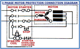
3 Phase Motor Protection Connection Diagram

[a] Electrical Connections – In three phase motors, the current in the three phases is not directly interrupted. Instead, the starter, contractor or other control circuit which switches on the three phases, is itself disconnected, stopping the motor. Hence, the thermostat located at the windings are wired in series with the magnet coil of the starter, contractor or other control circuit. Use 2 or preferably 3 thermal cut-outs (U.L. regulations of U.S.A. require 3 cutouts for a 3 phase motor), so that a thermostat is in touch with each phase winding to sense overheat in any phase individually. The thermal overload protectors are in, series with each other so that when any of them trips the circuit is interrupted. The leads of the thermal overload protector are guided individually or jointly to the motor terminal box to make the connections (See diagram). When temperature rises beyond the maximum permitted limit for the class of insulation of its windings (i.e, Class A, E, B or F), one of the thermostats will trip and the motor will stop. The smallest to the largest 3 phase motor can be protected this way and you only need to specify the insulation class of the motor. The thermostat rating is independent of the motor H.P. rating, because the thermostat handle only the light loads involved in operating the magnet coil of a starter, contactor or other control circuit. Hence, any size 3 phase motor can be protected.

[b] Installation – The thermal overload protector should be embedded in or tied to the phase windings so that one overload protector is located in each phase winding. The thermostats can even be tied to the overhang (with high temperature tape) so that there is good heat transfer from windings to the thermostats. Thus even existing motors can be provided protection, especially at the time they are opened for routine maintenance or rewinding. Avoid installing the motor thermal protector near any cooling air Flow. During the installation, while shaping the windings and fitting the end covers do not hammer or damage the protector or subject it to excessive stress.

Windings may be dipped in varnish and baked up to 150 degrees C after installation of the cut- outs.

[c] Ordering – When ordering Model BPM inform us of the H.P., insulation class (A, E, B or F).

 Voltage Up to 250V for ac motor or 24V dc motor
 Continuous Load Up to 8 AMPS
 Maximum Load Switching Capacity 30 AMPS
 Switching Action SPST Normally Closed (N.C.) contacts which open with a snap action at a  preset temperature and disconnect the motor starter from the mains and protect the motor.
 Flash-over Voltage Exceeds 2 KV between body & leads.
 Endurance (Life) Exceeds 100,000 operations (trippings).
 Trip Temperature Available preset for any trip temperature between 50 ± 5 C to 160 ± 5 C specified by customer. Trip temperature not adjustable.
 Reset Temperature Reset temperature (restart temp) approx. 15 ± 5 C below trip temperature.
 Restart Mode The motor will automatically restart upon cooling. Adequate precaution must be exercised in motor protection applications where automatic motor restart can cause injury, i.e., power tools, mixie blade, power saws, machinery etc.
 Fitting or Mounting The thermostat/thermal overload protector needs to be taped or tied on to the windings of the motor so that it can sense the temperature rise.
 Connections Thermostat/Thermal Overload Protector should be connected in series with the windings for motor protection of up to 1 H.P. motors. For protection of larger H.P. motors or 3 phase motors, one thermostat should be fitted on to each phase winding. All thermostats should be connected in series with each other and in series with the motor starter no-volt coil.

Transformer Protection

We are the leading manufacturer of Thermostat and Thermal Overload Protectors in India and we have developed two models of thermal overload protectors, i.e. Model BPM and Model ISQB, for over temperature and burnout protection of Transformers.

Transformer Protection Thermostat – Model BPM

Description of Model BPM

Model BPM thermal overload protector has been specifically developed for over temperature and burn-out protection of transformers, where the thermostat has to be fitted inside the windings. This thermal overload protector is a miniature marvel of precision engineering and it is the smallest thermal cut-out in our complete range of products. Due to its small size, this thermostat is very sensitive to temperature rise and ampere load and can be fitted inside the winding. As soon as the windings start heating up, this thermal cut-out senses the temperature rise and switches off at the pre-determined cutoff temperature, thereby, protecting the transformer from overheating or burning out . This pre-determined cutoff temperature is factory preset and cannot be changed. This thermostat has solid silver contacts for long life. The internal operating mechanism is all spot welded on a stainless steel housing plate. The outer body of this thermal overload protector is a high temperature resistant engineering polymer.

Out thermostats have a snap action bimetal strip and a beryllium copper switching blade which operate on the over center mechanism. This provides the thermostat with a quick restart characteristic, accurate trip temperature. This trip temperature does not drift downwards after long usage. The other snap action disc thermostats have delayed restart and the trip temperature does not stay stable and drifts downwards after continuous usage.

Special Features of Thermal Overload Protector:

  • Smallest physical size, easy to fit
  • Very sensitive to temperature rise
  • Snap action bimetal quick make and break action
  • Solid silver contacts for long life of 1,00,000 operations
  • No sparking or chattering of contacts
  • High temperature resistant teflon lead wires
  • Available for any trip temperature from 50C to 160C

Application

Model BPM thermostat is suitable for over temperature and burnout protection of transformers of all types. This thermal overload protector should be fitted inside the windings of the transformer. It can be fitted either in the primary side or secondary side of the transformer, which ever winding is heating up. When a fault condition occurs and the temperature of the transformer winding rises, the thermostat will sense this rise and switch off, thereby, protecting the transformer from burnout. For protection of small transformers with low power ratings, the thermal cut-out can be connected in series with the winding. For protection of large transformers with high power ratings, the thermal overload protector cannot be connected in series as the high current can damage the cut-out or it will cause nuisance tripping. The thermal cut-out needs to be connected to a relay, contactor, indicator, or control circuit, which will switch off the transformer when the thermal cut-out reaches its cutoff temperature and trips off. This cutoff temperature is pre-determined and cannot be changed. It depends on the insulation class of the windings as well as the size of the transformers, for example, insulation class B the trip temperature should be 130 degrees C and for insulation class F the trip temperature should be 150 degrees C. Please consult us for technical guidance and specifications.

Surface Mounting Model ISQB Thermostat/Thermal Overload Protector for Transformer Protection

Transformer Thermal Protection – Model ISQB

Description of Model ISQB

Thermal Overload Protector Model ISQB is suitable for protection where space is a constraint and the thermostat cannot be fitted in the windings. The thermal cut-out can be mounted on the transformer body with two screws. It has a solid machined aluminum outer body, which provides strength and quick heat transfer for sensing temperature rise. The body is electrically insulated so that there is no chance of any electrical shock. The internal switching mechanism is based on a snap acting bi-metal which results in quick make and break. This ensures that there is no sparking when the thermostat switches off or on.

Special Features of Thermal Overload Protector:

  • Easily mountable with two screws
  • Insulated outer aluminum body for strength
  • Snap Action bimetal thermostat
  • Quick heat transfer, no chattering or sparking
  • Solid silver contacts for long life of 1,00,000 operations
  • High temperature teflon lead wires

Application

This thermal cut-out can be mounted on either the inside or outside of the body of the transformer with two screws. When the body heats up or the temperature of the windings rise, this thermal overload protector will sense the rise in temperature and will trip off at a pre-determined temperature. For low current and power transformers, the thermal cut-out can be fitted in series with the windings. While, for high current and power transformers, the thermal overload protector needs to be connected to a relay or a control circuit, which will switch off the current when the thermal cut-out trips off. Please consult us for complete technical guidance.

Technical Specifications of Thermostat/Thermal Overload Protector for Protection of Transformers – Model BPM

 Voltage Up to 250VAC in primary or secondary winding
 Continuous Load Up to 8 AMPS
 Maximum Load Switching Capacity 30 AMPS
 Switching Action SPST Normally Closed (N.C.) contacts which open with a snap action at a  preset temperature and disconnect the transformer from the mains and protect it from overheating and burning out.
 Flash-over Voltage Exceeds 2 KV between body & leads.
 Endurance (Life) Exceeds 100,000 operations (trippings).
 Trip Temperature Available preset for any trip temperature between 50 ± 5 C to 160 ± 5 C specified by customer. Trip temperature not adjustable.
 Reset Temperature Reset temperature (restart temp) approx. 15 ± 5 C below trip temperature.
 Restart Mode The transformer will automatically restart upon cooling. Adequate precaution must be exercised in transformer protection applications where automatic transformer restart can cause injury.
 Fitting or Mounting Thermostat should be fitted inside the winding. It can be taped to the winding with high temperature tape.

Technical Specifications of Thermostat/Thermal Overload Protector for Protection of Transformers – Model ISQB

 Voltage Up to 250VAC in primary or secondary winding
 Continuous Load Up to 8 AMPS
 Maximum Load Switching Capacity 30 AMPS
 Switching Action SPST Normally Closed (N.C.) contacts which open with a snap action at a  preset temperature and disconnect the transformer from the mains and protect it from overheating and burning out.
 Flash-over Voltage Exceeds 2 KV between body & leads.
 Endurance (Life) Exceeds 100,000 operations (trippings).
 Trip Temperature Available preset for any trip temperature between 50 ± 5 C to 160 ± 5 C specified by customer. Trip temperature not adjustable.
 Reset Temperature Reset temperature (restart temp) approx. 15 ± 5 C below trip temperature.
 Restart Mode The transformer will automatically restart upon cooling. Adequate precaution must be exercised in transformer protection applications where automatic transformer restart can cause injury.
 Fitting or Mounting Thermostat/Thermal Overload Protector can be screwed on the inside of the body where it can sense the temperature rise and protect the transformer against burnout. If space is a constraint, it can also be screwed on to the outside, but care must be taken to protect it from external draft of air but covering it with some insulation, so that it does not get cooled by outside air flow.
 Connections Thermostat/Thermal Overload Protector can be connected in series with the primary or the secondary winding, whichever winding is overheating. For heavy load transformers, the thermostat needs to be connected to a control circuit, relay, contactor, etc., which will switch off the transformer when the thermostat trips off. This will protect the transformer.