1. Effect of amps load on trip temperature
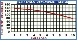
The amps load to which cutout is connected generates heat within the cutout itself. This self-generated heat will cause the cutout to trip earlier, i.e when surrounding of the cut-out is lower than the no-load trip temperature of the cut-out itself. The higher the amps load the lower the surrounding temperature necessary to trip the cut-out. In fact with a sufficiently large amps load the cut-out will trip even when the temperature surrounding it is room temperature, thereby protecting the equipment against severe overloads. This means that a cut out is sensitive to load current and as well as the surrounding temperature. This characteristic is very useful in applications like motors, transformers and other equipment which can get overheated due to excessive amps load caused by abnormal operating conditions like low voltage, locked rotor, overloading, single phasing, over voltage etc. In case of severe overloading the cut-out will trip off at a trip temperature much lower than it’s pre-set trip temperature calibrated to protect the equipment against over temperature damage caused by overheat above normal running temperature.
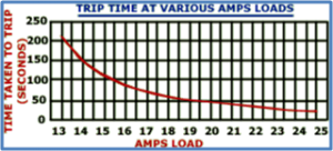
See following graphs showing approximate relationship between amps load, trip temperature and the time taken to trip . Loads upto 2 amps have practically no consequence on trip temperature. Similarly in 3 phase motors the above phenomena can be ignored because the cut-outs are in series with the starter or the contactor magnet coil, and therefore draw very little current. But in all other cases where the normal load exceeds 2 amps you must specify actual amps load to which the cut-out is connected during normal full load running conditions. Then we can provide correct calibration.
2. Selecting the Correct model
First determine from the illustrations which model is physically the most convenient to fit in your equipment.
Then determine the trip temperature required. Since the cut-outs are heat sensitive as well as current sensitive, you should let us know the actual current (in amps) of the circuit in which the amp is connected when the equipment is operating normally. This information is important only if the current exceeds 2 amps. Even though the current breaking capacity exceeds 30 amps , if your continuous normal load is more than 2 amps you should let us know the actual load to enable us to provide accurate tip temperature calibration. See note 1 above.
3. Application Instructions
Locate cut-out as close as possible to the heat source. Heat transfer between cut-out and heat source should be as good as possible. Avoid locating the cut-out where there is an air draft or other spurious effects. Cut-out may be fixed with a clamp, or with high temperature insulation tape or screws etc. For improved temperature sensing of flat surfaces use heat-sink compound between cut-out and surface for efficient and quick heat transfer. While fitting the cut-out, do not hammer or damage it or subject it to excessive stress. For motors refer to ?Engineering Notes? 10 &11.
4. Benefits of Using Thermal Cut-Outs
(a) High reliability and high quality can be provided in all electrical equipment by protecting against overheat and burnout damage at low cost.
(b) Complete protection of motors (single or three phase), transformers, coils etc. against over temperature and burnouts caused by abnormal conditions, i.e., power supply faults of over and under voltage, overload, single phasing, blocked ventilation, locked rotor, defective bearings etc.
(c) Permits the design of smaller, lighter and less expensive motors with considerable savings of copper due to reduced windings. With a PORTEX thermal protector the motor can now be designed for optimal performance during normal service conditions. The protector provides the built-in safety. Without a protector, more windings and a larger frame would be necessary to ensure slower heat rise and thus provide protection against abnormal conditions (functions that additional windings can do only imperfectly at higher cost).
(d) No starters for overload protection required as this function is carried out more effectively and efficiently by the protector.
5. Testing for Trip Temperature
Our cut-outs are 100% tested for trip temperature at several stages during assembly, and finally before dispatch. The most stringent quality control effectively ensures that only repeatedly tested pieces are dispatched. In case you wish to test trip temperature, you should employ an air circulation oven where the rate of temperature rise can be maintained at less than 1degreeC per minute. The cut-out should be connected to a test lamp and the trip temperature should be noted on an accurate thermometer whose mercury bulb is located near the cut-out in the oven. If an oven is not available an oil bath may be used, but care should be taken that the cut-out is inside a test tube which is kept dipped in oil. The cut- out itself should not be directly dipped in oil. The thermometer should be in the test tube along with the an-out. Rate of temperature rise should be very slow (less than 1 degree C per minute). A fast temperature rise will give wrong result.
6. Control Circuit Applications
In order to handle heavy loads use the thermal cut-out with a relay, contractor, starter or other control equipment.
7. Alarm or Signal Applications
Cut-outs can actuate an alarm, signal or buzzer in applications where it is not desirable to shut down the equipment.
8. Use of thermal cut-outs for maintaining temperature, i.e., as a Thermostat
Thermal cut-outs are mainly used for over- temperature protection, however. for maintaining temperature, use a thermal cut- out with a quick-restart characteristic, i.e., contacts dose and remake the circuit when there is a slight fall of temperature. This way you get the function of a non-alterable and preset thermostat at low cost. Write to us with full details of application, load, temperature etc.
9. A comparison of Thermal Cut-Outs with Over-current Devices for protection applications
External overcurrent devices (like starters or overcurrent relays) provide protection on the assumption that overheat occurs only due to overcurrent, so that they are set to trip at a certain current, say 115% to 125% of full load current. But overheat can occur for reasons other than over current, i.e., blocked ventilation, high ambients (like furnace areas), proximity to hot equipment. dust and dirt in the windings etc. Further, during sustained overloads, overheat may occur at less than the trip current of the over current device. A Portex thermal protector provides protection against all such conditions, and even allows the motor to carry more overload at low ambient conditions. Consequently, full protection is ensured, in addition to permitting complete utilisation of the motor’s overload capabilities. The thermal protector is considerably cheaper than external overcurrent devices. With a PORTEX thermal cut-out motor cost can be reduced by using a smaller frame size and lesser windings.
10. Technical Standing
All types of industrial and consumer equipment now incorporate thermal protection devices to provide high reliability and prevent overheat damage. Modern motors are generally fitted with thermal protection devices.
:: (Protectors) “commonly used on fhp and larger motors – are both current and temperature responsive. For larger motors pilot circuit protects located inside the motor open the holding coil circuit of the motor control contractor”. Machine Design 1975 Reference Issue on Electric Motors and Controls.
:: “Nowadays most fractional horsepower motors are being supplied with a built-in thermal protector, sensitive to both current and temperature”- C.G.. Veinott – Fractional and sub Fractional Horsepower Electric motors.
:: Thermally protected motors are compulsory in the U. S. before they are approved by Underwriters Laboratories Inc. (a U.S. standards institution) for many applications like fans, pumps etc. The U.S. standard for thermal protectors is U.L. 547-THERMAL PROTECTORS FOR MOTORS. Standards are also provided by the Canadian Standards Association.
11. Technical Assistance
Our technical assistance is based on our experience and the information in this catalogue believed to be true. Since we do not posses full access to data and designs of your products and applications, you should confirm suitability in all respects independently after adequate user trials. Responsibility is assumed by us neither for customer product design and functioning, nor for any infringement of patents and rights of others following our technical assistance.